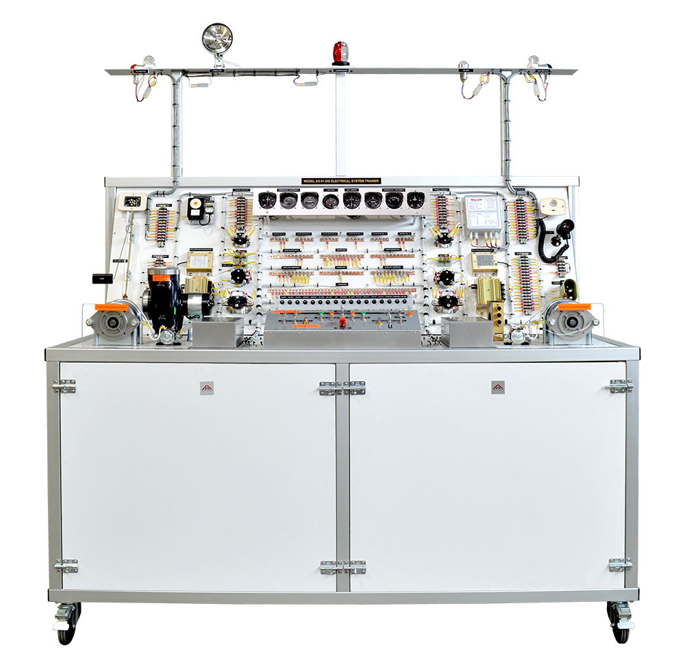
AS-51 Aircraft Electrical System Trainer
The aircraft electrical system trainer is an ideal resource to teach about an aircraft multiengine electrical system. By using this trainer, students not only learn the functionality of each component, but they also develop logical and systematic approach to perform troubleshooting tasks. The system is laid out to depict a typical aircraft electrical system, and contains standard aircraft components and wiring. Model AS-51 is a complete functional simulation of a dual-engine 28V DC electrical system of a typical turbine aircraft.
Model AS-51 trainer has been designed to teach the students both parallel generator bus configuration (like DC-10, Boeing 727, etc.) and split bus configuration (like Boeing 757, Boeing 767, MD-80, Airbus A320, etc.). Instructor can switch the main bus configuration simply by flicking a switch. This unique feature is not available from any other manufacturer.
System Features:
The trainer Model AS-51 in dual generator configuration comprises of:
Note: The system components listed above are for Model AS-51-DG (dual generator system). Model AS- 51-SG (single generator version) has fewer components but it can be readily upgraded to dual engine configuration
- Two Independently Driven 28V DC Generators
- Two Interconnected Generator Control Units
- Switchable main buses configuration between Split Bus System and Parallel Bus System (DG models only)
- Avionics Relay and avionics bus
- Two solid-state Generator Control Units (GCU)
- Typical Cockpit Instrumentation, Circuit Breakers, and Controls
- Representative Loads
- Two Main Bus-bars for each generator
- Two Auxiliary Bus-bars
- Battery Bus-bar
- Two 115 V @ 400 Hz Bus-bars
- Two 26 V @ 400 Hz Bus-bars
- Parts used are aircraft components
- Battery charging system
- Faults incorporated by instructor to teach troubleshooting techniques
- Voltmeters (two) and Ammeters (three)
- Distribution terminal strips (six)
- Instructor’s manual & Students’ manual with wiring diagrams
- Computer-based Training (optional)
- APU Input Plug (one)
- Dual Solid State Inverters to produce 115 VAC @ 400 Hz and 26VAC @ 400 Hz
- Low noise enclosure for generators
- Comprehensive safety features, e.g. emergency shutdown
AeroTrain trainers may be customized as per customers’ request. If you would like any additional features incorporated in our standard system, we will be glad to do so.
Specifications:
Battery:
- Aircraft sealed, 24V battery
- Aircraft DC generator rated 28VDC @40A/50A at 3600 rpm, driven by 230 VAC/50 Hz Motor.
- Electronic Controlled Generator Build-up
- Electronic Field Controller/Switching
- Current Limiter
- Reverse Current Protection
- Paralleling / Equalizing
- GCU induced Over Voltage (OV) Protected
- Voltage Regulation: 28.4V + 0.4V
- Max Field Current: 3A.
- Aircraft Starter 24 VDC
- Two Static Inverters, each rated 50VA minimum.
- No.1 Generator Bus-bar 28VDC
- No.2 Generator Bus-bar 28VDC
- Two Auxiliary Bus-bars 28VDC
- Battery Bus-bar
- Ground Bus-bar
- Two bus-bars 115VAC @ 400 Hz.
- Two bus-bars 26VAC @ 400 Hz.
- Two AC Neutral Bus-bars
- Avionics bus-bar
- Landing Gear Motor
- Cabin Air Blower
- Avionics Blower
- Electromechanical Actuator (Optional)
- Navigation Lights (Right Wing, Left Wing, Tail)
- Strobes (Right Wing, Left Wing, Tail)
- Rotating Beacon
- Landing/Taxi Light
- Cabin Light
- Reading Light
- Multifunction Cockpit Light with Dimmer
- Leading Edge Sensor (Vane type)
- Audio Warning Horn
- Independent Battery for SWS
- No.1 Generator Voltmeter
- No.1 Generator Ammeter
- No.1 Generator Hourmeter
- No.2 Generator Voltmeter
- No.2 Generator Ammeter
- No.2 Generator Hourmeter
- Battery Ammeter
- Fuel Gauge
- Aircraft wires, with clear identification labels for each wire.
- All wires are coded and labeled for troubleshooting.
- Demonstrates aircraft standard wiring practices
- All electrical signals are accessible to students through terminal strips
- Mains AC circuit breakers, manual switch, and starter switch.
- Guarded Switch for Master Power
- Parallel/Split Bus Selector
- Starter Selector
- Generator / Alternator Selector
- Inverter Power Switch
- Internal / External Lighting Switches
- Instrument Power Switch
- Landing Gear Motor Switch
- Cabin Air Switch
- Avionics Blower Switch
- 10 x 10 inches access panel mounted in the back.
- Sixteen fault insertion switches
- Master Power Indicator
- Generator Status Indicators
- Inverter Status Indicators
- Bus Configuration Indicator
- Generator Out Warning
- Stall Warning System aural warnings
- User’s Manual (Colored, 42 pages)
- Study Guide (Colored, 65 pages)
- Instructor’s Guide (Colored, 15 pages)
- Computer-Based Training (15 hours) Our system trainers are supplied with computer-based training (CBT) as an optional item at additional cost.
- Hinged Control Panel for quick and easy access to internal wiring for demonstration and maintenance.
- Hinged Circuit Breaker Panel for quick and easy access to internal wiring for demonstration and maintenance.
- Two large access doors for the motor and generators.
- Rear access panel for battery compartment.
- Easy access for components removal and installation by one person using common hand tools.
- Dual ventilating fans installed in generator / motor cabinet.
- Fire-resistant soundproofing installed in generator / motor cabinet.
- Triple-protection for AC power.
- All circuits have dual levels of protection using circuit breakers at source and load.
- Power distribution area protected by transparent cover with access holes to all bus-bars.
- All terminal strips protected by transparent covers.
- All moving parts covered with transparent covers.
- Clearly visible safety warnings.
- Low noise cabinet for generator and AC electrical motor.
Electrical Trainer is available in two configurations as below:
- Model AS-51-DG: Dual Generator System
- Model AS-51-SG: Single Generator System
- Dual Generator System: 65 L x 33 D x 64H inches
- Single Generator System: 40L x 33D x 64H inches
- Dual Generator Syetem: 700 Lbs.
- Single Generator System: 600 Lbs.
- Mounted on four heavy-duty casters.
- Rugged and durable metal-frame construction